BPMN elements
Elements are the building blocks you use to create processes.
There are five main element categories in a diagram. Every element represents a unique aspect of a business process.
You find information on specific elements in the BPMN Element Reference.
| Category | Element Type | Description |
|---|---|---|
| Flow Elements | activities, events, gateways | Define process behavior |
| Connecting Elements | sequence flows, message flows, associations, data associations | Connect flow elements to form a flow |
| Swimlanes | pools, lanes | Assign participants (organizational units, people or systems) to activities |
| Data Elements | data objects data inputs, data outputs, data stores | The data required, produced, stored or collected in a process |
| Artifacts | text annotations | Provide additional information about a process |
Element attributes
Every element has a set of attributes that you can edit.
Some attributes are essential if you want to run a BPMN model in Process Manager. Attribute descriptions are important if you want a comprehensive process report.
You edit attributes in the Attributes panel.
Every element has an Attributes tab. Depending on the element, the Attributes panel can have additional Attribute tabs. For example, a User Task has an Attributes tab and a Conditions, Input, Output, Resource and Property tab.
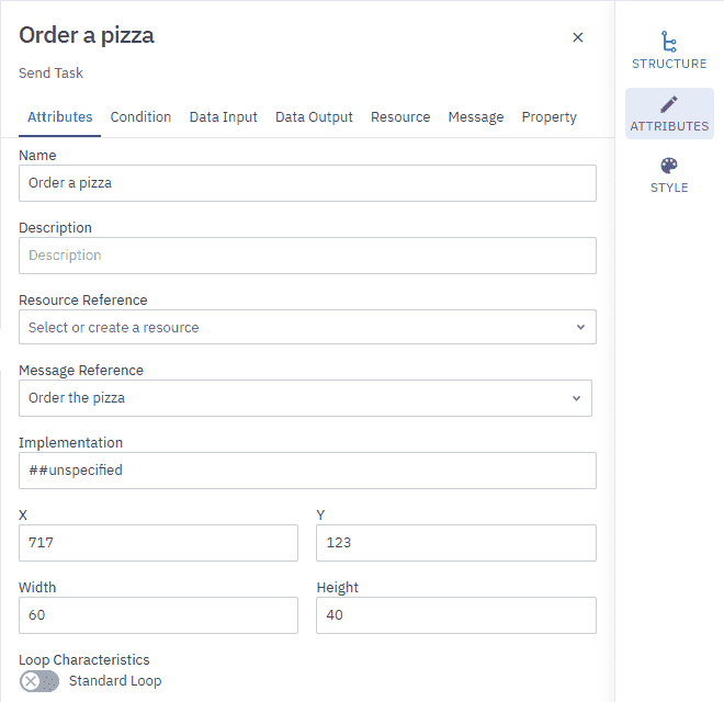

Open the Attributes panel
- Select the element in the diagram, and in the Configuration panel, click Attributes.
Add elements
There are several ways to add elements to a diagram.
-
From the Elements tab in the Navigation panel
-
Using the Ring
-
Using the Magnetic Edge tool
Here you can also learn how to add elements to Pools and Subprocesses.
Elements tab
The Elements tab in the Navigation panel contains all the elements you can use in a diagram. Elements are divided into categories so you can easily find the element you’re looking for.
To add an element:
-
In the toolbar, click
to open the Navigation panel. -
In the Elements tab, select an element, then drag and drop it onto the diagram.
The Ring
The Ring is an interactive context menu that helps you to create processes faster than manually dragging and dropping elements.
The Ring has two parts: a right menu for adding and automatically connecting elements, and a left menu with tools to edit an element. The actions and tools available in the Ring depend on the element you select. Hover over icons to see tooltips that describe what they do.
Here’s an example of how to add a Start Event and connect it to a User Task using the Ring:
-
Right-click on the diagram to open the Ring.
-
In the right Ring menu, select the Event icon, then select Start Event.
The Ring stays open and is ready for your next action.
-
Select the Tasks icon, then select Task.
The Ring automatically connects the Start Event to the Task. Alternatively, you can hold and drag the Task into position.
-
To change the Task to a User Task, keep the Task selected. In the left menu select
 then select User Task.
Copy and paste
You can add elements by copying an existing one and pasting it elsewhere.
-
Select the element you want to copy.
-
In the left Ring menu, click
. -
Click an empty space on the diagram to open the Ring, then click
.
Other ways to copy and paste
-
Toolbar: Use the copy
and paste actions. -
Keyboard shortcuts: Ctrl + C to copy and Ctrl + V to paste.
Magnetic edge
The Magnetic Edge tool automatically connects elements as you drag and drop them onto your diagram. Think of it like a magnet; it connects to the closest element.
-
In the toolbar, click
. -
Drag an element from the Elements tab and drop it onto the diagram.
-
Drag another element close to the first one. The Magnetic Edge tool will automatically connect them when they’re positioned correctly.
To deactivate the tool:
- In the toolbar, click
.
Add elements to Pools
You add elements to Pools in the same way that you add elements to a diagram.
However, there are some rules to know before you start:
-
Sequence Flows can’t cross Pool boundaries
-
Message Flows can cross Pool boundaries.
-
Message Flows can’t connect to objects that are within the same Pool.
Add elements to Subprocesses
You add elements to Subprocesses in the same way that you add elements to a diagram.
However, there are some rules to know before you start:
-
Sequence Flows can’t cross Subprocess boundaries
-
Message Flows can cross Subprocess boundaries.
-
Message Flows can’t connect to objects that are within the same Subprocess.
Model a data flow
Data flows define how data moves between activities and events and data elements in a process.
Data associations move the flow of data between data elements and the activities and events in a diagram.
A data association can have a data object reference, data input, data output or data store reference at one end as its source or as its target. The Data Input or Data Output of the flow element is at the other end of the Data Association.
You can model and edit a data flow using the Data flow tool or do it by manually modeling and editing it.
Data flow tool
Manually modeling data flows in complex processes can be error-prone and time-consuming. The Data Flow tool simplifies this by:
-
Guiding you through the creation process
-
Automatically validating associations
-
Highlighting errors before execution
You can model data flows starting from a single activity/event or two activities/events.
Before you begin
-
Define the data inputs and data outputs for each activity or event.
-
Ensure that data types (item definitions) match between connected elements.
From one activity or event
You can model a data flow starting with a single activity or event and associate it with multiple data inputs and/or data outputs.
The following is an example that starts with a single user task and creates a data input association and one data output association.
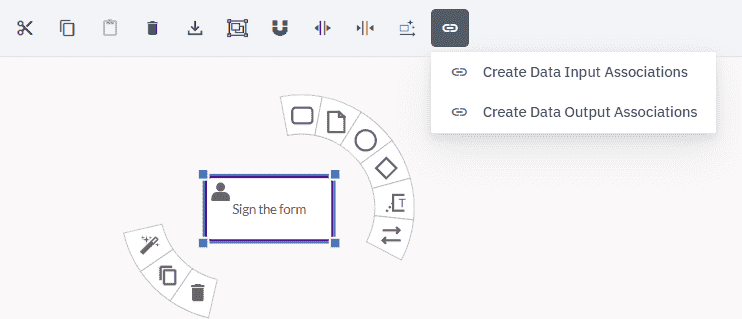

-
Select the user task.
-
In the toolbar, click
and select Create Data Input Associations. -
Select a data input association for the user task, then click Create.


-
Select the user task again.
-
In the toolbar, click
and select Create Data Output Associations. 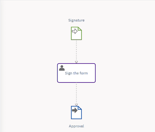

Between two activities or events
The following procedure is an example of how to model a data flow between two user tasks.
The example maps the flow of data that starts at the signing of a travel request form (‘Sign the form’) and ends with the request being approved (‘Approve travel request’). The aim is to associate the data outputs of ‘Sign the form’ with the data inputs of ‘Approve travel request’ and associate them using data elements — in this example, data object references. The data inputs and data outputs have previously been defined.
-
Select the two User Tasks.
-
In the toolbar, click
and select the source of the data flow. The source, Sign the form, is the starting point for the flow of data.
The data flow tool is disabled until you select an activity or event.
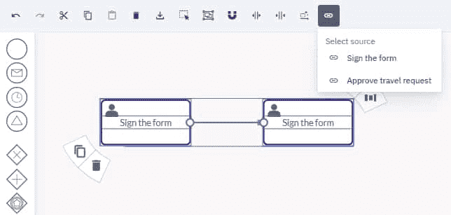

In the dialog box that opens, data associations are automatically created between the data outputs and data inputs of the two tasks.
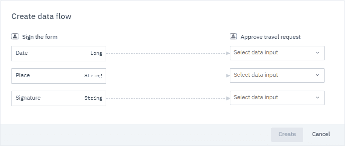

-
Select the data inputs to be associated with the data outputs.
When you select a data input, a data element is automatically created on the data output of the task.
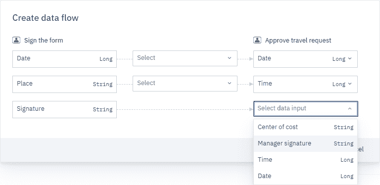

-
Select the data element type.
In this example, it’s a data object reference.
Type the name of a data element in the field to find it faster.
You can also create a data element by typing a name in the field and selecting the type of data element.
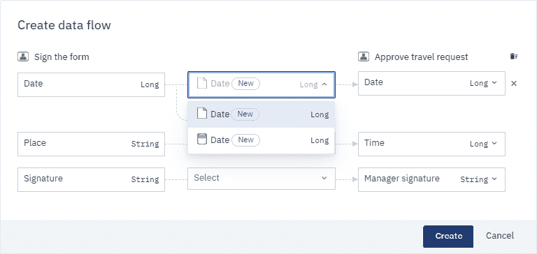

-
Once you’ve associated all the data inputs with data outputs, click Create.
The data flow should look something like this:
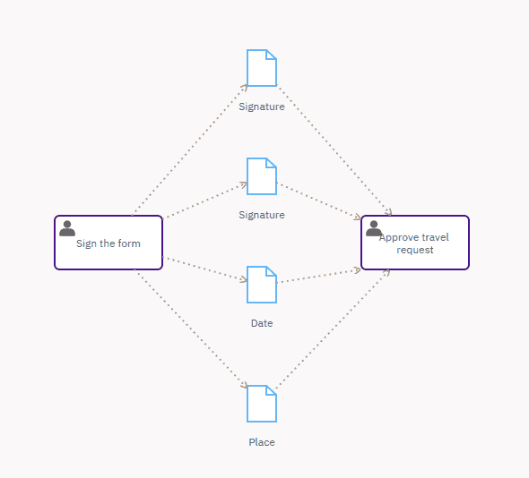

Manually create a Data Flow
To manually model a data flow you need to define the following elements in a diagram:
- the data element
- the activity or event
- the data association connecting the data element to the activity or event
Before you configure a data association, you need a data element and an activity or event in the diagram that has a data association between them.
The order set out in this procedure is purely for the purpose of example. You can define the data association, data element and activity or event in the order you prefer.
For detailed information on how to define a specific element and its attributes, see the documentation for that element.
-
Define the Data Element
Select the data element and define its attributes.
If you use a data object reference or a data store reference, you need to associate it with a data object or a data store.
You can create a new data object or data store in the Attributes of the data object reference and data store reference:
-
Click New.
-
In the panel that opens, fill in the Name and (optional) Description fields and specify the Data Type (Item Definition) and Default value.
-
Click Create and select.
-
-
Define the Data Association
The direction of the arrowhead of the data association determines whether the data element is a source for, or a target of, the activity or event.
In the Attributes tab of the data association:
- Click
and select the Source Reference or the Target Reference from the dropdown list or create a new reference.
To create a new reference:
-
Click New.
-
In the panel that opens, fill in the Name and (optional) Description fields and specify the Data Type.
-
Click Create and select.
- Click
Tools for editing elements
There are several tools you can use to edit elements in a diagram.
You can use them to create space between elements, align them, select elements, delete them and more.
Edit with the Ring
You can use the left menu of the Ring to edit elements.
Depending on the element you select, the Ring contains the editing tools you can use for that element.
Hover over icons to see tooltips that help you understand the actions they perform.
| Tool | Icon | Description |
|---|---|---|
| Edit element type |  |
The options available depend on the type of element. |
| Copy | Copy the element. | |
| Paste | Paste the element. | |
| Delete | Delete the element. | |
| Add label |  |
Add labels to elements that don’t have room for an internal label. |
| Edit label |  |
Edit labels. |
| Collapse Supbrocess | Collapses the Subprocess and hides its contents. | |
| Expand Subprocess | Expands the Subprocess to show its contents. |
Auto Layout tool
The Auto Layout tool automatically tidies up your diagrams by evenly aligning and spacing elements and connections. It enables you to create visually consistent and comprehensible diagrams and saves you time and the effort of manually moving elements into the proper position.
To automatically tidy up your diagram:
- In the toolbar, click
.
Create space tool
You can use the create space and remove space tools if you need to create space for additional elements or reduce the diagram size.
Create space
-
Click
. The moment you activate the tool, guides appear in the diagram.
-
Position the pointer over the area of the diagram where you want to create space.
-
Click, hold and drag in the direction you need to create space — horizontally or vertically — then release.
To deactivate the tool, click
again or press ESC.
Remove space
-
Click
. -
Position the pointer over the area where you want to remove space.
-
Click, hold and drag in the direction you need to remove space — horizontally or vertically — then release.
To deactivate the tool, click
again or press ESC.
Whiteboard shapes
Whiteboard shapes provide a flexible set of visual elements you can use to annotate, organize, and collaborate directly on your BPMN diagrams. These shapes appear on the canvas but aren’t included in the underlying BPMN model, so you can be creative without affecting your process.
To add a shape:
-
In the toolbar, click
to open the Navigation panel. -
In the Elements tab, under Whiteboard shapes, select a shape.
-
Drag and drop it onto the diagram.
Select elements
There are several ways to select elements in a diagram.
You can select an element by clicking on it or by using the Rectangular Selection or Select All tools.
Once you’ve selected the elements you can move, copy, delete or align them.
Rectangular selection tool
This tool enables you to select multiple elements in the diagram.
-
In the toolbar, click
 .
. -
Click and drag the pointer to define an area around the elements you want to select.
To deactivate the tool, click
 again or press ESC.
Select all tool
This tool enables you to select all the elements in the diagram.
-
In the toolbar, click
 .
.To deactivate the tool, click
 again or press ESC.
Align elements
You can align and distribute one or multiple elements using the Ring or align and distribute them manually using guides and margins.
Align with the Ring
Use the Ring to align elements vertically or horizontally.
When you align elements vertically you can also align them to the right, left and in the center.
When you align elements horizontally you can also align them at the top, bottom or in the middle.
-
Select the elements you want to align.
-
Use the alignment options in the right Ring menu.
Align manually
If you’re adding elements from the Element Palette you can use the guides that appear to help you align the elements.
Vertical and horizontal guides appear when you drag and drop an element near another element. Margins also appear to help you distribute the elements evenly.
Delete elements
To delete elements in a diagram, select the element or elements:
-
In the toolbar, click
. -
In the Ring, click
. -
Use the keyboard shortcut Ctrl + X.
Undo and redo
When you’re adding elements to a diagram and editing them it can be useful to undo and redo your actions.
You find the undo