Attributes
The Attributes panel shows the attributes for each BPMN element. These attributes vary depending on the element type and define its key properties, behavior, and appearance.
Called Element
Specifies the process or task that the call activity invokes.
To set a called element:
-
In the Called element field, click
to show the list of available processes. -
Select a process from the list.
Code
Defines a script to be executed during process execution for supported elements.
To configure code:
-
Click
to expand the Code section. -
Configure the following fields:
Field Description Script format The script language or format. Code The script code to be executed
Condition
Defines an expression that controls whether an element is triggered during process execution.
To set a condition:
-
Click
to expand the Condition section. -
Turn on the Default condition toggle to designate this as the default sequence flow when no other path conditions evaluate to true.
-
Select the condition type to define how the condition is evaluated:
Type Description None No condition is defined. Binary Compares two data elements or values using a logical operator. - First operand: The first data element or value for comparison.
- Operator: The logical or mathematical operator used to evaluate the relationship between the operands.
- Second operand: The second data element for comparison.
Free A custom condition expression without strict syntax restrictions. This type isn't executable. - Language: The specific language used for the expression.
- Expression: The Boolean expression that must evaluate to true for the sequence flow to trigger.
Data Input
The data inputs used by the element.
To add a data input:
-
Click
to expand the Data Input section. -
Click Add data input.
-
In the dialog box that opens, configure the following fields:
Field Description Name The name of the input. Description A description of the input. Item Definition The data type of the input. Default value The default value of the input.
-
To edit an existing data input, click its name in the list and make your changes.
-
To remove a data input, click
next to the data input you want to delete.
Data Object
Specifies the data objects that are read, written, or updated during the execution of a Process.
To define a data object:
-
Click the Data Object field to open the dropdown menu.
-
Complete one of the following actions:
-
Assign an existing data object: Select a data object from the available list.
-
Create a new data object: Click
New data object.
-
-
If creating a new object, in the dialog box that opens, configure the following fields:
Field Description Name The name of the data object. Item Definition The data type of the data object. Default value The default value of the data object. Description A description of the data object.
-
To edit an existing data object, click its name in the list and make your changes.
-
To remove a data object, click
next to the data object you want to delete.
Data Output
Specifies the data outputs that are produced by the element.
To add a data output:
-
Click
to expand the Data Output section. -
Click Add data output.
-
In the dialog box that opens, configure the following fields:
Field Description Name The name of the output. Description A description of the output. Item Definition The data type of the output.
-
To edit an existing data output, click its name in the list.
-
To remove a data output, click
next to the data output you want to delete.
Data State
Defines the state of a Data Object Reference at a specific point in the process — for example, “in progress” or “completed”. How you define the state is your choice.
The state appears in the diagram as part of the Data Object Reference label.
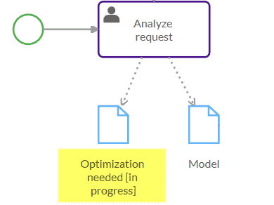
To define a data state:
- In the Data State field, enter the state text.
Data Store
Represents a location where data is stored and accessed during process execution. A data store models persistent data that can be read or written by multiple process instances or tasks.
To define a data store:
-
Click the Data Store field to open the dropdown menu.
-
Complete one of the following actions:
-
Assign an existing data store: Select a data store from the list.
-
Create a new data store: Click
New data store.
-
-
If creating a new data store, in the dialog box that opens, configure the following fields:
Field Description Name The name of the data store. Item Definition The data type of the data store. Description A description of the data store.
-
To edit an existing data store, click its name in the list and make your changes.
-
To remove a data store, click
next to the data store you want to delete.
Default value
Sets a default value for the referenced data input.
Description
Adds an optional description for the element. Descriptions are useful if you want a comprehensive process report.
Direction
Defines whether an Association shows a direction.
To set the direction:
-
Select one of these options:
Option Description None No direction is shown. This is the default. One A single arrowhead points from the source object toward the target object. Both Arrowheads are displayed at both ends of the association line, indicating a mutual relationship.
Error Reference
Specifies the error ID associated with the element.
To define an error reference:
-
Click the Error reference field to open the dropdown menu.
-
Complete one of the following actions:
-
Assign an existing error: Select an error from the available list.
-
Create a new error: Click
New error.
-
-
If creating a new error, in the dialog box that opens, configure the following fields:
Field Description Name The name of the error. Error Code Enter the specific error code identifier. Item Definition The data type of the error. Description A description of the error.
Escalation Reference
Specifies the escalation ID associated with the element.
To define an escalation reference:
-
Click the Escalation reference field to open the dropdown menu.
-
Complete one of the following actions:
-
Assign an existing escalation: Select an escalation from the available list.
-
Create a new escalation: Click
New escalation.
-
-
If creating a new escalation, in the dialog box that opens, configure the following fields:
Field Description Name The name of the escalation. Escalation Code The unique code used to match a specific throw event to its corresponding catch event handler. Item Definition The data type of the escalation. Description A description of the escalation.
Executable process
Marks the element as executable.
- Select the Executable process check box to enable execution.
Implementation
Specifies the technology used to send or receive messages.
Choose from:
| Option | Description |
|---|---|
| WebService | A web service technology or URI that identifies other technology or coordination protocol. |
| Unspecified | The specific implementation technology or protocol is left undefined. |
Interrupting boundary type
Indicates whether the Boundary Event is interrupting or non-interrupting.
- Select the Interrupting boundary type checkbox to cancel the activity after the Boundary Event is.
Item Definition
Specifies the data type of the item referenced by the data input or data output.
- Click
to open the list of available data types and select one.
Lane
Specifies the lanes used in a Process.
To add a data lane:
-
Click
to expand the Lane section. -
Click Add lane.
-
In the dialog box that opens, configure the following fields:
Field Description Name The name of the lane. Description A description of the lane.
-
To edit an existing lane, click its name in the list and make your changes.
-
To remove a lane, click
next to the lane you want to delete.
Loop
Controls loop behavior for repeating activities by defining a condition and the maximum values for the loop behavior.
The condition is evaluated at the beginning or at the end of every loop iteration.
A looped activity has a loop marker:
To configure loop behavior:
-
Click
to expand the Loop section. -
Click Add loop.
-
In the dialog box that opens, configure the following fields:
Field Description Check condition at start A configuration setting to evaluate the loop condition at the beginning of each iteration. Description Functional notes explaining the specific purpose and behavior of the loop. Max iterations The numerical limit on the number of times the cycle can repeat. Condition The Boolean expression that controls the loop. The activity will continue to iterate as long as this evaluates to true. If this expression is missing or syntactically invalid, the loop can't be executed by the process engine.
Message Reference
Specifies the message ID sent or received by the task.
To define a message reference:
-
Click the Message reference field to open the dropdown menu.
-
Complete one of the following actions:
-
Assign an existing message: Select a message from the available list.
-
Create a new message: Click
New message.
-
-
If creating a new message, in the dialog box that opens, configure the following fields:
Field Description Name The name of the message. Item Definition The data type of the message. Description A description of the message.
Name
Specifies the name shown in the element label.
Position
Defines the element’s exact coordinate location (X and Y) on the diagram.
To set the position:
- Enter specific coordinate values or use
to adjust manually.
Property
Allows you to define properties for flow elements. A property is a container for data that belongs to a specific element in the Process.
To set a property:
-
Click
to expand the Property section. -
Click Add property.
-
In the dialog box that opens, configure the following fields:
Field Description Name The name of the property. Description A description of the property. Item Definition The data type of the property. Default value The default value of the property.
-
To edit an existing property, click its name in the list and make your changes.
-
To remove a property, click
next to the property you want to delete.
Resource Reference
Specifies the ID of the resource associated with the activity.
To define a resource reference:
-
Click
to expand the Resource reference section. -
Click
New resource. -
In the dialog box that opens, provide a name and a description.
-
To edit an existing resource reference, click its name in the list and make your changes.
-
To remove a resource reference, click
next to the resource reference you want to delete.
Signal Reference
Specifies the ID of the signal that is broadcast.
To define a signal reference:
-
Click the Signal reference field to open the dropdown menu.
-
Complete one of the following actions:
-
Assign an existing signal: Select a signal from the available list.
-
Create a new signal: Click
New signal.
-
-
If creating a new signal, in the dialog box that opens, configure the following fields:
Field Description Name The name of the signal. Item Definition The data type of the signal. Description A description of the signal.
Size
Defines the physical dimensions (width and height) of the element on the diagram.
To set the size:
- Enter specific dimensional values or use
to adjust manually.
Source Reference
Identifies the source of a Data Association. The source can be a Data Object, Data Input, Data Output or Data Store.
To define a source reference:
-
Click the Source reference field to open the dropdown menu.
-
Complete one of the following actions:
-
Assign an existing source: Select a data output from the available list.
-
Create a new source: Click
New data output.
-
-
If creating a new source, in the dialog box that opens, configure the following fields:
Field Description Name The name of the data output. Item Definition The data type of the data output. Description A description of the data output.
Target Reference
Identifies the target of a Data Association. The target can be a Data Object, Data Input, Data Output or Data Store.
To define a target reference:
-
Click the Target reference field to open the dropdown menu.
-
Complete one of the following actions:
-
Assign an existing source: Select a data input from the available list.
-
Create a new source: Click
New data input.
-
-
If creating a new target, in the dialog box that opens, configure the following fields:
Field Description Name The name of the data input. Item Definition The data type of the data input. Default value The default value of the data input. Description A description of the data input.
Text
Provides an annotation with additional information about an element or the entire diagram.
Text Format
Specifies the format of the annotation text. Default value: text/plain.
To format text, use the tools in the Style panel.
Timer event definition
Sets conditions for triggering timer events.
-
Click
to expand the Timer event definition section. -
Click Add timer event definition.
-
In the dialog box that opens, select a timer type:
Type Description None No timer type specified. Recurring date Repeated on a specific day and time in a cycle — for example, "every Monday at 9am". Fixed date A specific date and time — for example, "31 December 2021". After duration The time from the moment the Process reaches the event to the moment the trigger is fired — for example, "5 minutes". -
Enter the value in the Expression field.
Refer to the ISO 8601 standard for date, time, and duration formats.
-
If required, specify the expression format in the Language field.
-
To edit an existing data output, click its name in the list.
-
To remove a data output, click
next to the data output you want to delete.
Visible marker
Controls marker visibility. For clarity, keeping markers visible is recommended.
- Select the Visible marker check box to show the marker.